I am a Boy Scout in Troop 73. For my Boy Scout Eagle Project, I installed a solar-powered welcome sign at Marin County (Gnoss Field) Airport. Above is a video that shows the overall process I went through for this project.
The Process
The following pictures and descriptions will give a more detailed account of each step along the way. After the pictures, you can also find: statistics about my project (hours/money spent), an article written in the Marin County Volunteer View, the operating/maintenance guide I wrote, and more!
|
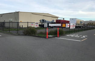
I installed the solar-powered welcome sign at the entrance to Marin County Airport, Gnoss Field, and this is a picture of the location before I started working on my welcome sign. The small patch of grass was used for the sign because it is easily visible when driving on the long road coming into the airport. The first design constraint the airport manager gave me was that the welcome sign had to be completely off-grid because there was no access to electricity there.
|
|
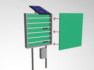
To get approval, I needed to include a design in my proposal. I created my design using Autodesk 3ds Max because its animation capabilities allowed me to show how the components of my sign came together. Shown in the picture is the original CAD design of a ready-made metal sign frame with fluorescent lights. Throughout the whole process, it was challenging to design and specify parts to use in my project because I had never worked on an off-grid solar or sign construction project before. I learned to reach out to others who could help me with their expertise. This preliminary design was suggested to me by the airport manager.
|
|
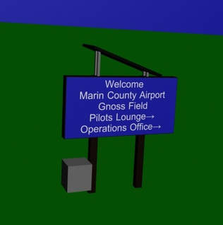
After approximately 15 design iterations, I solidified this final CAD design which was used for construction. You will notice there are many changes from my initial design. First, the sign is now landscape instead of portrait, which better displays the text and keeps the weight lower for structural stability. Second, the original design specified a ready-made metal box with fluorescent lights included. The final sign ended up being just the acrylic sign face, so I had to build a custom sign frame out of wood. Third, because there were no fluorescent lights included, I had flexibility with my lighting choice and decided to pick more efficient LED lights.
|
|
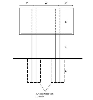
Before installing the pressure treated 6” x 6” wood posts, I sketched up a design in Google Drawings. Since both the sign and frame were large and heavy (over 500 pounds of weight combined), I had to ensure that the posts would be structurally sound. I also had to account for the strong winds that Gnoss Field airport is notorious for having. To handle these conditions, I decided to dig post holes 18” in diameter and 4’ into the ground, which I verified with a structural engineer.
|
|
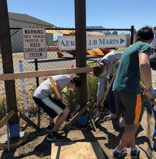
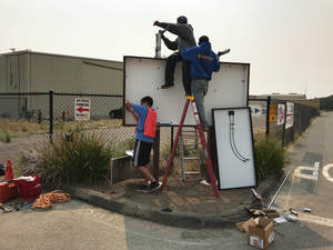
The first work day at the airport was for installing the two 6x6 posts. I asked other Boy Scouts to help me mix and pour 1500 pounds of concrete to fill the post holes. Luckily, I had an electric concrete mixer to speed up the process! I also learned how to use sonotubes to create a nice finished look at the top of the concrete. Before that day, I found out from a professional in construction that concrete contains carcinogens, so I told everyone to wear masks.
|
|
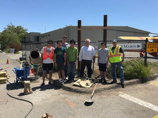
After a long day of hard work in the sun, the posts were installed. I used some scrap 2x4 to hold the posts in place while the concrete dried. In this picture, you can see the group that helped me, including other Boy Scouts, and Harry, who works for the Marin County Department of Public Works. Throughout my project, I received help from many industry professionals who taught me all kinds of new skills that will help me in my future projects as a maker.
|
|
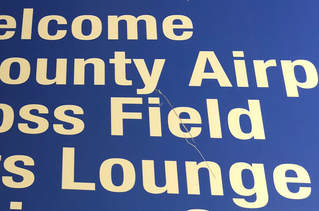
When the acrylic sign face was ordered and arrived, a large gash ran across the surface, as shown in the photo. This probably occurred in shipping, so it did not seem like a big deal; we requested a new sign to be re-shipped. However, the second sign had some delays in shipping, and it arrived damaged too. Finally, the third sign shipped and arrived unscathed. While this was a seemingly minor setback, it actually delayed my schedule by over a month because of all the waiting that ensued from the multiple shipments.
|
|
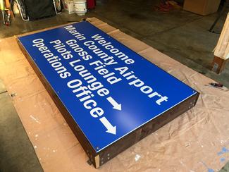
I constructed the wooden sign frame in my garage. I made the frame with pressure treated wood and marine grade plywood because it was the most economical option. The sign was so large (8’ x 4’) that using wood ended up being a challenge due to the flexible nature of the long pieces. Every time the sign face was taken off, it took some tweaking to get it to fit back into the frame because the wood had warped slightly. The final time that I put the sign face back into the frame, I had to use a Fein oscillating cutter tool to rout out wood to make the sign fit.
|
|
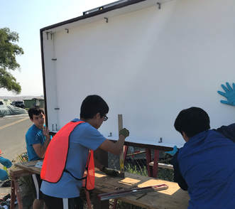
The second work day at the airport was for mounting the sign frame to the posts. I had some people stabilize the frame, while others made sure that it was level. I secured the frame to the posts using 3 through bolts and one large industrial L-bracket per post.
|
|
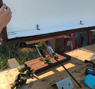
Due to the somewhat flexible nature of the wood, I had to ensure that the frame was mounted without putting undue stress on it. In order to keep the sign frame in place and modify the height of the left or right side, I used car jacks that could be adjusted up and down. This worked out really well since the frame was too heavy and awkward to hold up by hand.
|
|
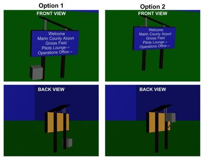
On the second work day, I also wanted to install the battery box that would house the electrical components. You can see from the CAD models in this picture that I came up with two different options. Option 1 has the battery box low on the side of the post, allowing for easier maintenance access while distributing the large weight of the batteries closer to the ground. Option 2 has the battery box high on the back of the post. There was not enough space to put the box lower on the back because a fence was in the way. It would have to be eight feet above the ground, limiting maintenance access. This also adds 150 pounds up high on the post, which would decrease structural stability. Originally, the airport manager liked option 2 because he felt it would make the box less visible, but after we discussed the pros and cons of the options, we chose option 1.
|
|
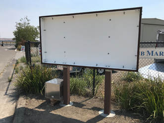
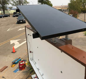
This is a photo of the site after the second work day. The sign frame and battery box are now mounted on the posts in the optimal positions. Also, all parts are now painted. The exterior wood is painted with a special brown used by Marin County in public works projects. I painted the interior of the frame white in order to reflect the light from the LEDs.
|
|
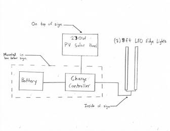
Once the posts and sign frame were in place, I could install the electrical components. This is a line diagram detailing the overall idea of my electrical system. The key part here is that this solar system does not require an inverter, because all current is DC (direct current). In residential systems, inverters are needed to convert DC to AC (alternating current) because we use AC in our homes, but in this off-grid system, the only load is the LEDs powered by 24 volt DC. The charge controller is used to charge the batteries from the solar panel during the day and allow the LEDs to draw from the batteries at night.
|
|
|
This PDF contains the specification sheets for the solar panel, charge controller, LEDs, and battery. To specify parts, I started with the 230 watt SunPower solar panel that was donated to me and looked for a compatible charge controller. I found the Morningstar SunSaver MPPT with help from a solar engineer. It is designed for off-grid battery systems, and the maximum charging current (15 amps) and PV open circuit voltage (60 volts) both accommodated my solar panel. Next, I asked a lighting designer to help me find compatible LEDs. He directed me to Aion LED and suggested that I pick a color temperature around 4000 Kelvin. After searching through datasheets, I picked the 8924-40-WR. Lastly, I needed a battery. I learned that off-grid systems are designed to be able to operate for a few days without energy generation, so I selected a large capacity battery. If my solar panel stops generating power, my LEDs could potentially run for around 5 nights on a fully charged battery.
|
|
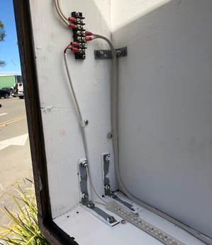
On the third work day at the airport, I installed the first part of the electrical system, which was the waterproof LED strings. Both of the eight foot strings terminate into a terminal block that has a positive and negative wire going back to the battery box. The LED strings are wired in parallel, and since they are dimmable, I am running them at 20 volts instead of 24 volts, which lowers the daily energy consumption by 100 watt-hours. In the winter, there is less daylight and therefore less solar energy generated, but the LEDs actually have to run longer because there are more hours of darkness. When I connected up the LEDs in the summer, there was no problem with energy consumption. But, I read the specifications sheets for the LEDs and researched online data about solar insolation and irradiance in my local area, and I realized that I had to dim the lights to ensure that the LEDs would be able to operate fully during winter months.
|
|
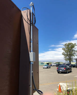
This is the conduit running along the back of the post. The very top is a weatherhead that allows for solar photovoltaic wires to transition from the exposed air to inside the conduit. The head’s shape ensures that no water enters the conduit. The conduit connects to a junction box that takes wires from the solar panel and the LEDs, routing them to the battery box. I used ½” electric metallic tube (EMT) conduit, which just barely fit my wires. So, when pulling wires through the EMT, I had to neatly group the wires so they would fit through. It took numerous attempts to successfully feed all the wires through.
|
|
On the fourth work day at the airport, I installed the solar panel with help from Garvin, a solar installer at Sun First Solar, a local solar company. I was grateful to have his help because he was familiar with the mounting hardware and gave me tips on how to connect the solar panel to my system. He suggested that I tilt the solar panel at 15 degrees using the mounting stanchions. This is slightly lower than the statistical “best” tilt, but Garvin said that it would work better in my situation due to the design of my project and the materials we had available. Additionally, the panel is oriented with a 185 degree azimuth, almost due south. Since we are in the northern hemisphere, the sun is in the southern part of the sky, so that is the ideal direction to point solar panels.
|
|
At the end of the fourth work day, I had finished installing the solar panel, LEDs, and conduit. The only steps left at this point are the electrical components that go in the battery box (batteries, charge controller, and timer) and the installation of the sign face.
|
|
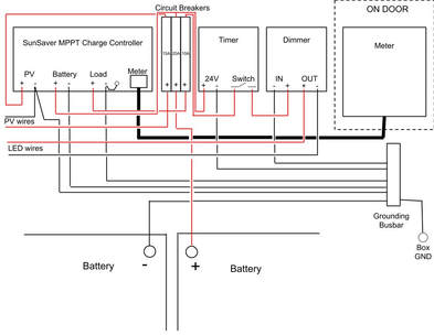
I looked over the electrical component manuals to create this diagram detailing the wiring connections. The charge controller is the central hub of the system that connects the PV solar panel, batteries (in series), and LEDs. The charge controller can turn the LEDs on and off at sunset and sunrise, but I wanted more control over the timing system to turn the LEDs off during late hours when there are no visitors to the airport. So, I added a timer that runs on the 24 volts from the battery at all times. It has a contact inside that connects the load connection on the charge controller with the dimmer that goes to the LEDs, and it closes the contact to turn on the lights. The electrical components run on a relatively low voltage (24V), but I still wanted to ensure the safety of anyone that may work on my sign, so the circuit breakers provide overcurrent protection. Additionally, the electrical components are all grounded with a ground lug in the battery box.
|
|
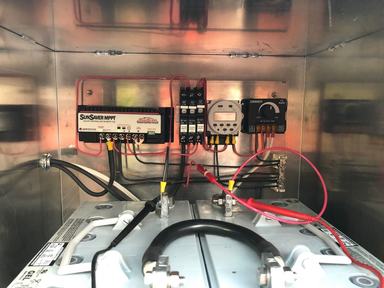
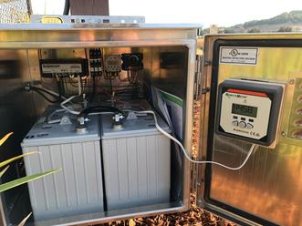
Here are the electrical components discussed in the previous schematic. The components are all inside the waterproof and locked battery box mounted on one of the sign posts. A conduit is connected to the battery box from the left side, bringing the black PV solar wires and white LED wires into the box to connect to the charge controller. In this picture, you can also see the extra black and red leads coming from the bottom of the image. These are multimeter leads which I am using to test the voltage of the electrical system. I learned from a past electrical project, the magic LED switch box, that I should do a neater job when wiring because it was hard for me to fix issues when my wires were really messy. So, I tried to make my wiring as neat as possible to make maintenance easier in the future.
|
|
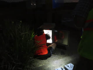
To complete the commissioning of the project, I went out to the airport at night to monitor the system and record data such as the voltage of the panel and batteries. I wanted to ensure that it was functioning as intended at night before I set the timing program and turned on the LEDs. Also, when tracking the data, I realized that it would be helpful to have a meter on the system to record the data for me, so I researched and obtained a meter that could connect to my charge controller.
|
|
I attached the meter to the door using velcro and a wood block. The meter displays information such as voltage and current for the solar panel, battery, and the load. There is also data logging for the previous 30 days. By analyzing the data history, I confirmed that the load (LEDs) consistently uses less energy than the solar panel generates. When I checked, the solar panel had generated about 150 amp-hours more than the LEDs had used.
|
|
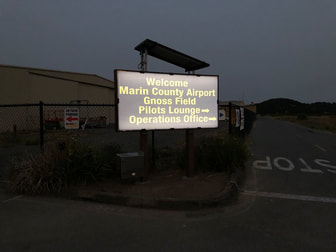
Here is the completed sign at around 9pm on a summer day, so the LEDs had just turned on at sunset half an hour before. The program that I uploaded to the charge controller determines when sunset occurs by checking when the solar panel voltage drops below 42% of the maximum recorded voltage. Since the open circuit voltage is 48.2 volts, sunset is determined to be when the panel drops below 20.2 volts. With this program, I make the LEDs turn on at sunset every day and turn off at 11:45pm. Then, the lights turn back on at 5:30am and turn off at sunrise, which is when the voltage rises above 25.5 volts (53% of the open circuit voltage).
|
|
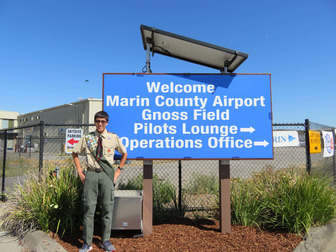
I put on the finishing touches by laying wood bark to make the area look nicer. After 114 hours of my time and $4200 in funding and donations, my project was complete! As the first solar installation at the airport, my luminous welcome sign greatly interested my community. County Supervisor Judy Arnold applauded my project at a Board of Supervisors meeting, an article in the Marin County Volunteer Newsletter described my efforts, and SunPower wrote a blog about my application of solar energy (see below for article and blog link). When I witnessed the sign’s vibrant LEDs blaze to life for the first time, I felt proud of my success and contribution to my community.
|
Project Statistics
|
Hours Logged:
By Me: 114 hours By all collective people involved: 303 hours Volunteers: Almost 30 different people were involved in the creation of this project, including fellow Boy Scouts, adult Scout leaders, and industry professionals. |
Funding:
County of Marin Budget: $3550 Donated Items (estimated worth): $650 Total Estimated Cost of Project: $4200 Building: 9+ months 4 different full build days |
Donors / Contributors
A Special Thanks to the following groups/organizations for their role in this project!
Marin County Airport and the Department of Public Works
Sun First Solar
O'Mahony and Myer
Associated Lighting Representatives
Scouts and Adults from Troop 73
Gnoss Field Community Association
SunPower
Boy Scouts of America
and my friends and family!
Marin County Volunteer View Article
My Eagle Project has caught the attention of many people in the airport and County community, and I have presented the video of my project to various groups/people. Here is an article in the Volunteer Newsletter for Marin County that was written about my project. Note that while the title says "Intern," I was not an Intern for the County, I think that I just got that title because my Eagle Project is categorized as volunteer work for the County, as Gnoss Field Airport is owned by Marin County.
If the above PDF does not load, here is the link: https://www.marincounty.org/-/media/files/departments/hr/volunteernewsletter/2018/september.pdf
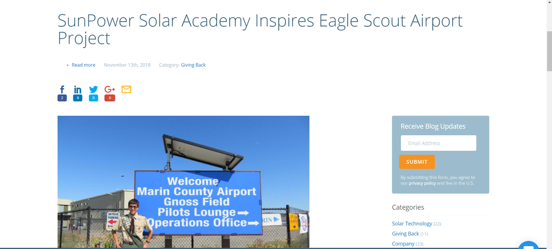
SunPower Blog Post
SunPower was very impressed by my project, and they wrote a blog post regarding my project, which can be found here:
us.sunpower.com/blog/2018/11/13/sunpower-solar-academy-inspires-airport-project/
us.sunpower.com/blog/2018/11/13/sunpower-solar-academy-inspires-airport-project/
Upon completing construction, I wrote up operating and maintenance instructions which I left in the battery box, in case anyone else ever needs to work with the sign or electrical components. The document can be found here;
Here is a copy of my project proposal that was presented to the Boy Scout Board that approved my project. Note that some things, such as the design, have changed because the sign dimensions changed per request of the project beneficiary. The updated 3D models can be seen above.
Let me know what you think! Please contact me with any comments or questions!
